And now on to a much cooler topic: 3D printing. They are pretty futuristic even when you aren't using them along with space tech. But we are...
Computer Aided Design
Where do we Start?
To get fabricating, you need designs to realize. You can always make fun figures and other artistic stuff in Blender, but what if you need something precise? Enter openSCAD. This is the most popular "scripting" CAD software (as opposed to visual designers like Autodesk Fusion or AutoCAD that are more popular with makers but harder to learn and less satisfying for programmers). Though some nice alternatives have sprung up in recent times. OpenSCAD is still the king if you intend to collaborate or create models that webapps can consume and customize. Especially because it has a highly compatible Javascript implementation.
This blog isn't an openSCAD tutorial, I'm about the discuss the design process. If it catches your interest, you can check out the very detailed Wikibook or find tons of tutorials on YouTube. This is another point where openSCAD is leaps and bounds ahead of other scripting CAD solutions.
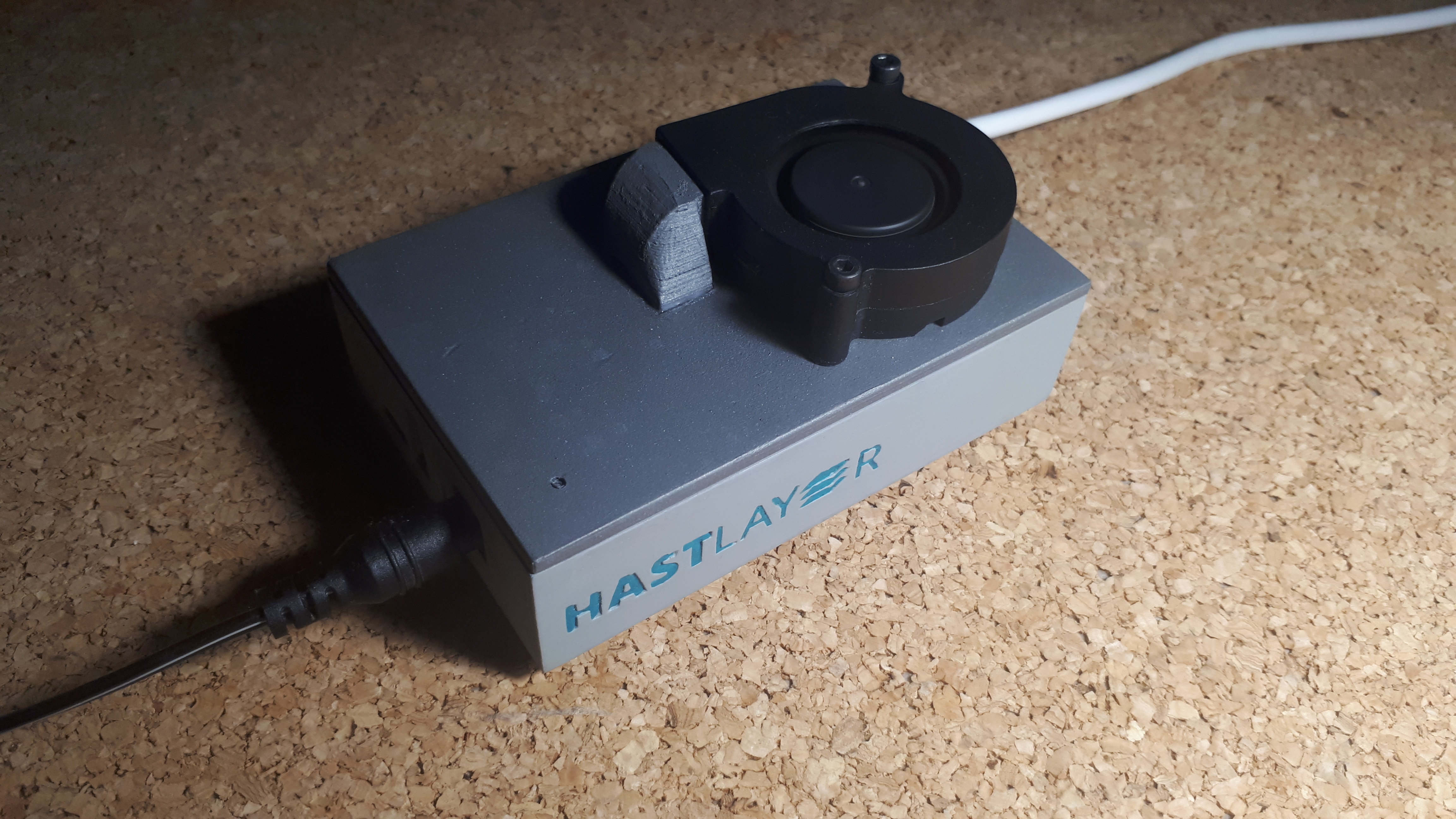
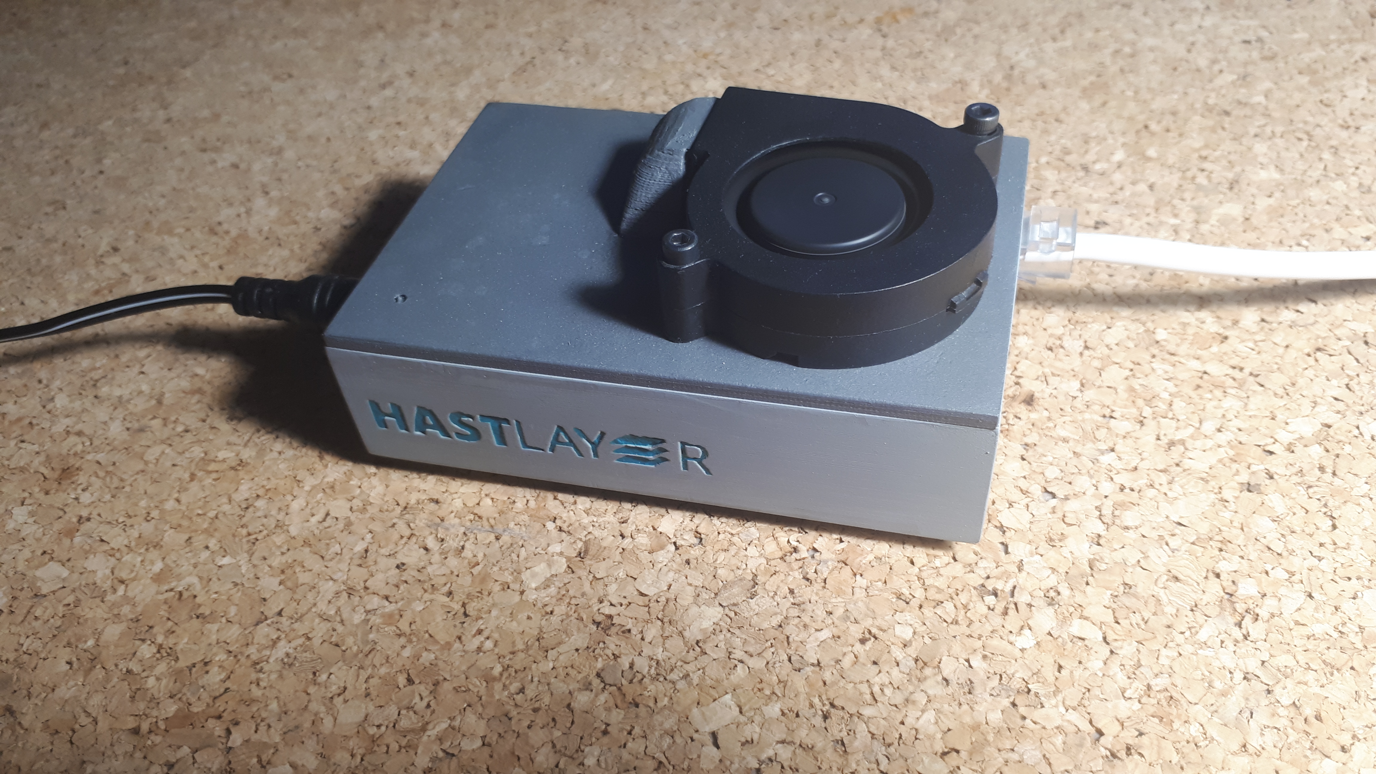
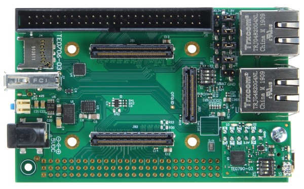
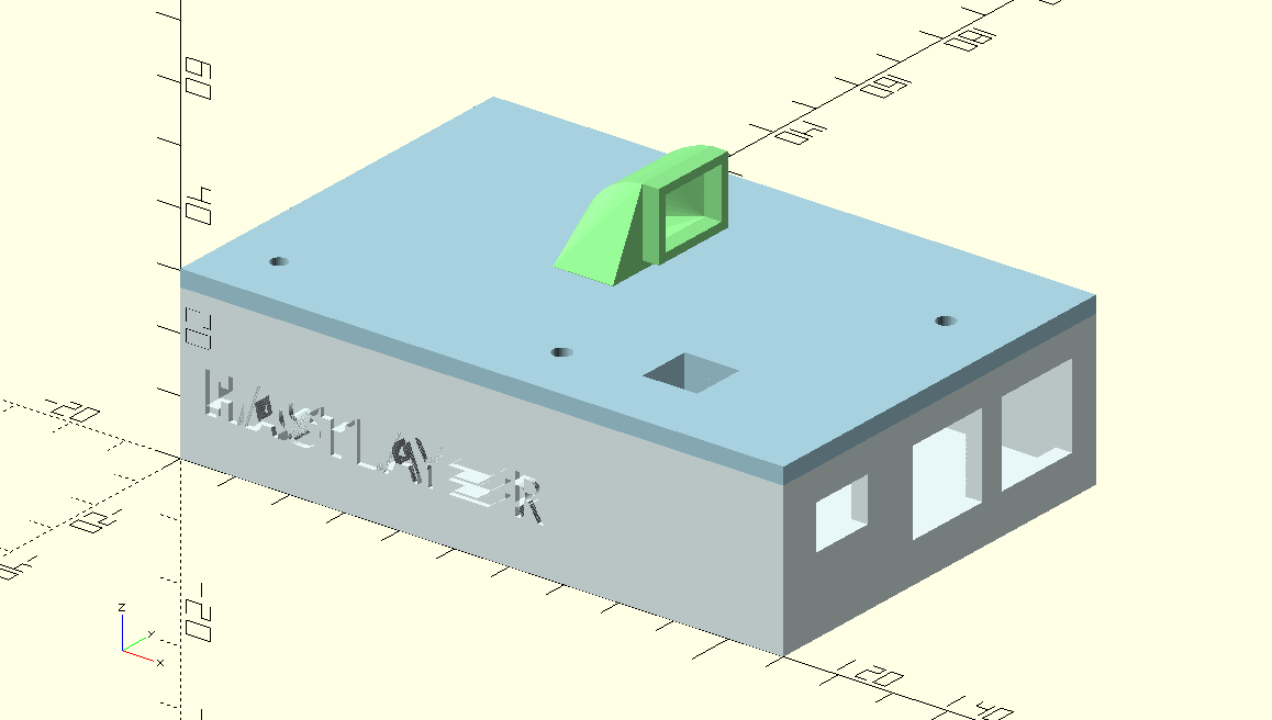
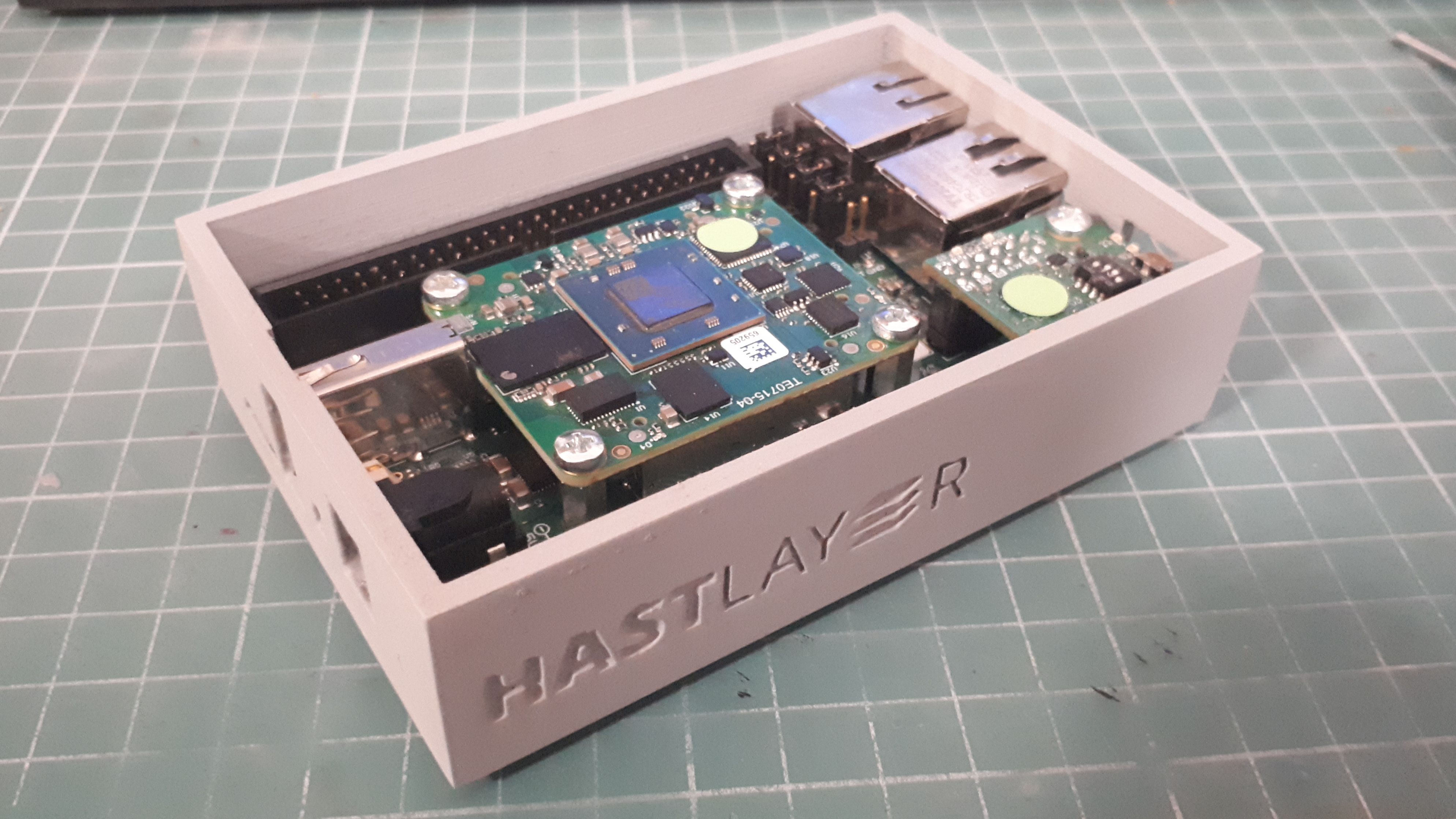
Today I will talk about making an enclosure for a single board computer. In this case a Trenz Electronic board with a Xilinx Zynq-7000 FPGA accelerator I got lent to use for Lombiq's .Net-to-FPGA solution called Hastlayer. This is a dev board for the same tech whose radiation hardened cousins we should be able to use in satellites so it's really breaking new frontiers. Also it's a good opportinity to check out how you can add branding to your creatong without too much hassle.
Preparation
They say measure twice, cut once, but it's even better if you don't have to measure physical objects. If you can find good quality top and side photos you are golden. When it comes to solid components you have a good chance to find such pictures on the manufacturer's website or store. Then you only have to measure one dimension of the board to get the physical size of a pixel and work with pixels in your document. (I saved that into a variable called phy_div in this project.)
Though sometimes you can't find such pictures and you have to break out the calipers. This makes me sad, because mine is garbage. So now it's really time to measure twice or even more! If you have one pic and only need to measure the other dimensions not covered by it, then you can multiply your millimeters by phy_div to get pixels. This way you can stay in a single unit system.
I've measured the 2D dimesions of the board, its screw holes and port locations from the top-down picture in their webshop and I used calipers to measure the height of the ports and their distance from the main board. This is all the information needed to set the required holes for the enclosure.
The Principlies: Carving and Gluing
OpenSCAD subscribes to the idea of making your model from primitive objects like cubes and couponers cylinders. You perform a series of simple operations like translate, scale or rotate on these shapes. Then you can use Boolean operations to carve (difference), glue (union) or to cut away the non-overlapping parts (intersection). Each operation can contain a block of shapes in it and the Boolean operation is applied to them sequentially.
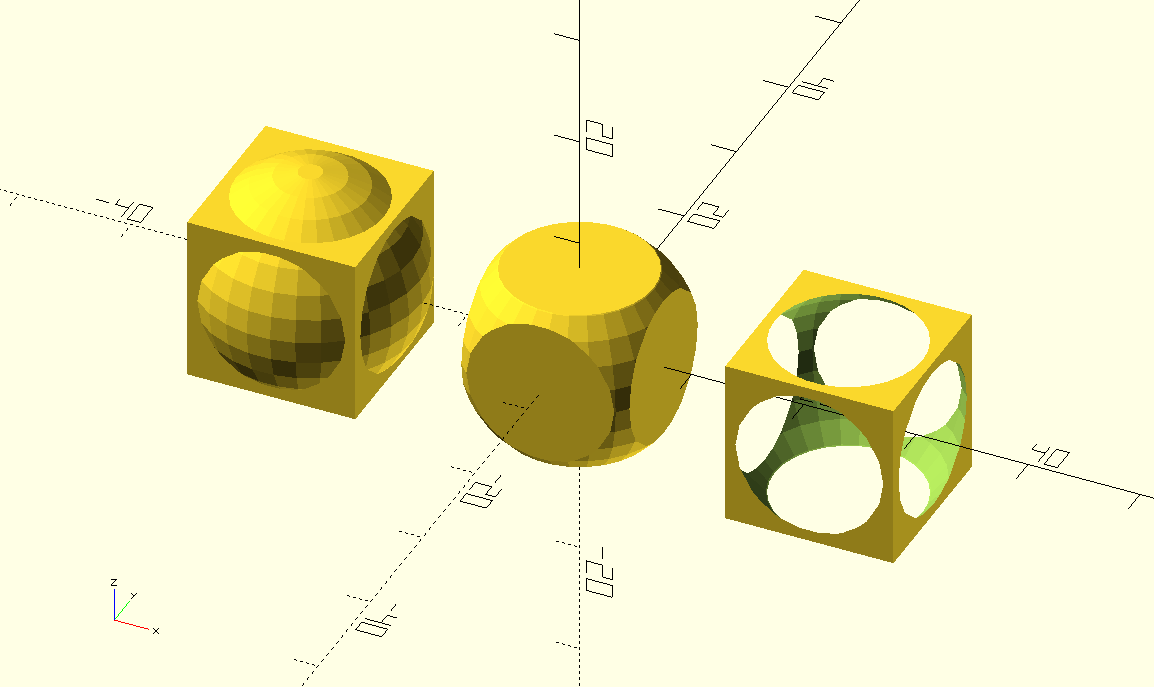
For example, to make a box you can create two centered cubes. Slightly scale up the first, then take the difference of the two.
difference() {
	scale(1.1) cube();
	cube();
}
This gives you a hollow box. If you also translate the second box up a bit you get a lidless container. All these simple operations add up.
What to Look out for?
The goal is to create a box with a ridge for a lid, screw posts, and holes for the IO ports. Later also a lid and a funnel/air duct for a fan. It's important to write every measurement into variables. Not just because you may have to use the same twice (eg. we have 2 Ethernet ports with the same width) but also because things have a tendency to get out of hand in terms of complexity. Later you will woder what that number was for. Better to add 2 or 3 variables and have longer code than to worry about what it means later.
You can also use modules, to create reusable bits or simply to organise certain shapes within the model. You can also use modules to cut perfectly interfacing parts by using difference on your stock with the module of the other part (difference() { cube(); my_module(); }). Everything you write outside of the modules is considered your output. If you are working with modules don't forget to actually instantiate them!
If you measured in pixel units, then you must apply scale(1/phy_div) { ... } to your final output to get back into physical coordinates that your printer can understand. You can do this inside the slicer program too, but this is more reliable.
Versions
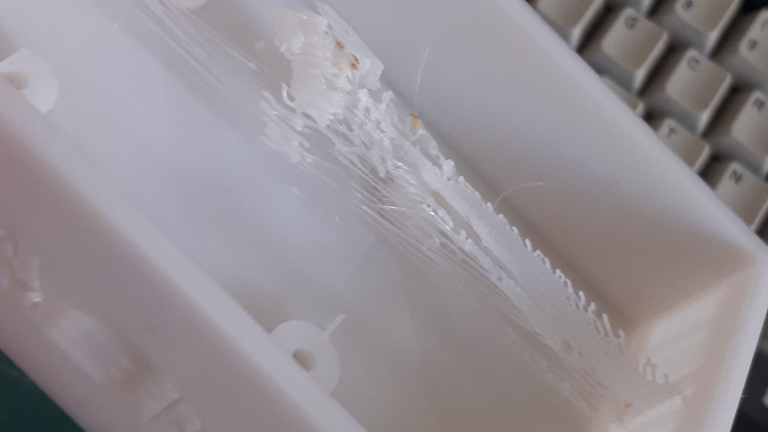
Designing things is an iterative process, it's ok to not have it perfect on the first go. In this project my first attempt was just the bottom part, a one-side-open box with port holes and screw posts. I didn't realize that there was an SMD capacitor right next to one of the screw holes that interfered with its post so I couldn't lay the board flat. Things like this happen, you will be glad if you have a soldering iron. Not for any soldering, but the material of the printed plastic is malleable to heat so we can correct these mistakes. If you don't have one, a heated knife can work as well. This trick can also be used to embed nuts into the object - that way the screw is in place more reliably and won't strip its thread over time. The insides of the shapes are mostly empty. The printer uses one of many possible hash-like patterns for internal support, so when you heat up part of the object you can easily push it in and get rid of such obstructions. This is good enough to patch up prototypes. In the next iteration I've already added a block of difference there to avoid this interference.
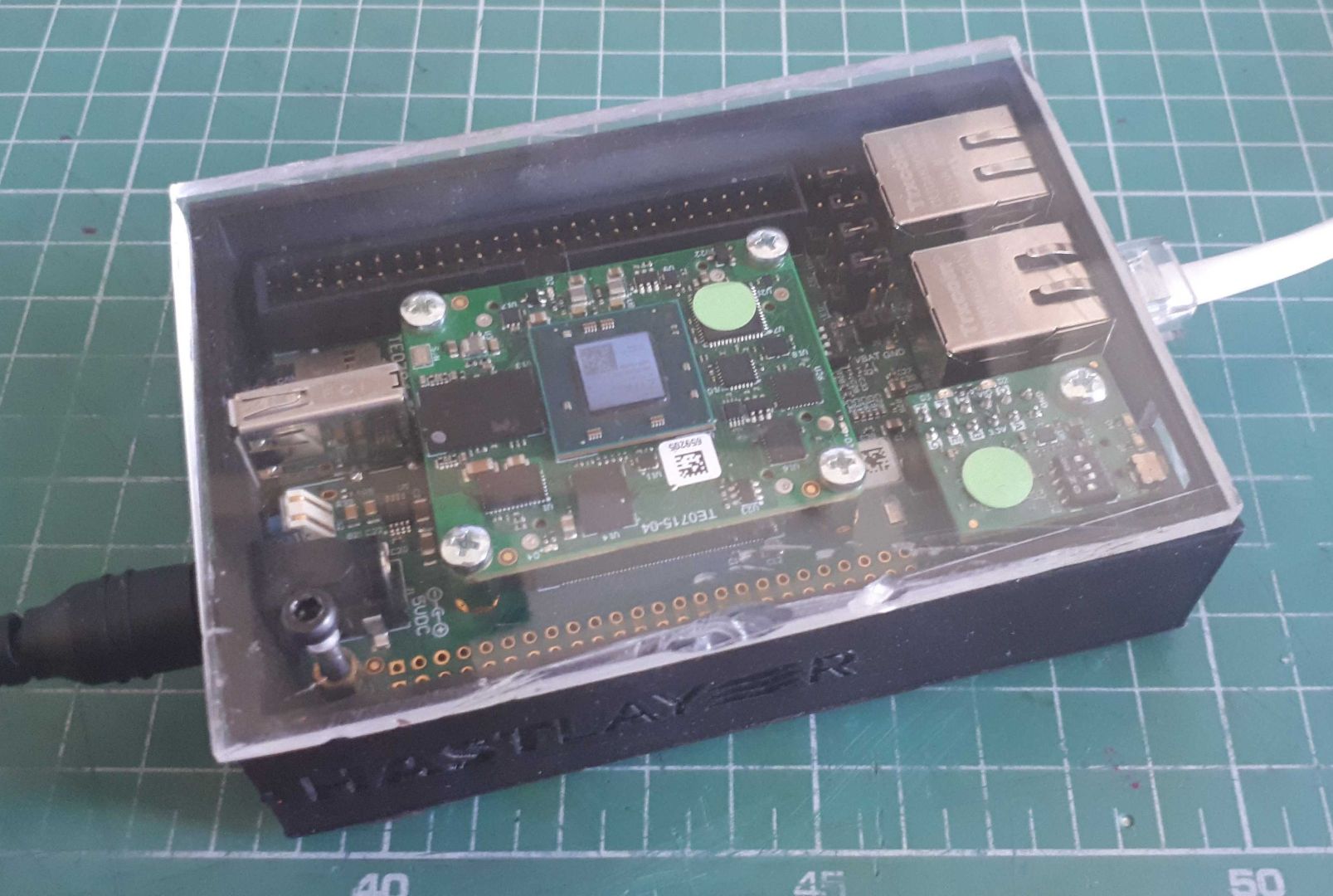
Not all problems are mechanical. My first successful instance used an acrylic sheet as the top cover that can swivel open. This kept the dust out, but it also trapped the heat in! The top got concerningly warm during use. So I found myself using it "open" most of the time which kind of defeats the purpose. So I started working on the next version with active cooling. I had some leftover small 5V centrifugal fans - the kinds 3D printers use to cool their hot end. Normally you don't need to cool this board so this fan is well overqualified for this task even when not running at full volts. I plugged it into the 3.3V pin on the board's exposed GPIO and it ran almost silently with decent speed. Enough to push the warm air out through the gaps around the ports.
To get the fan on the board I had to ditch the swivel opening for a screw-in top with an intake right above the CPU/FPGA module. That's pretty much in the top center so in case of a direct connection the fan wouldn't fit without overhanging which would make it impossible to fasten to the top. I had to design a duct that connects the fan's exit hole with the lid's intake hole. This took a bit of an advanced openSCAD technique that I have only learned while doing this project called hull. Essentially it takes two or more objects (can be coplanar 2D shapes or and 3D objects including very slightly extruded non-coplanar 2D shapes) and tightly wraps them in tarp. The result is a convex shape connecting the two.
The lid was another thing where the first try didn't work out. These cheap fans have roughly the same shape but they aren't exactly identical so you can't perfectly trust any sample you find online. The trick is to just brute force it during assembly. You can read about that in a bit.
Now the SBC is only mildly warm instead of worryingly toasty. But performance has a cost. I had to replace the appealing "glass" top with a plastic one because I don't have the tools to carve a shape with a lip in acrylic.
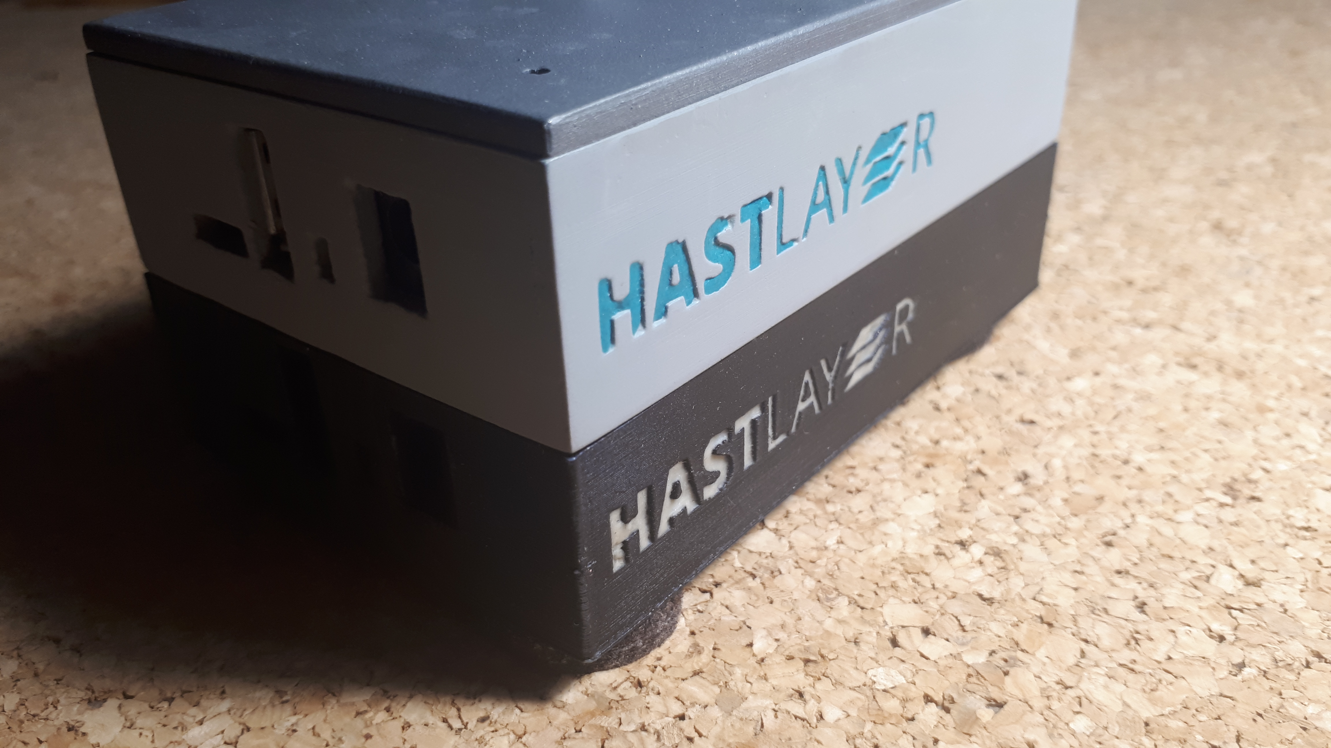
Branding
An interesting consideration, how do you put some drawing or logo on your part? Luckily openSCAD got our back here. You can take any grayscale PNG image and turn it into a surface height map style. Then slightly extrude it, translate and scale to where the target surface is and use union or difference to make it embossed or indented respectively. I did the latter, so I can put some colored filler in the recess.
translate([50, 10, 50])
	scale([1,10,1])
		rotate([90,0,0])
			linear_extrude( 3.6)
				projection(cut = true)
					translate ([0,0,70])
						surface(file = "hastlayer-logo-tagline-120h.png", center = false, invert = true);
Open Source
Yeah, the whole code is here, if you want to check it out. Hope it helps.
Computer Aided Manufacture
Printing
Aside from the first prototype, each print was made with the highest resolution my Anycubic I3 Meta can handle.This was mainly for the benefit of the branding, but it also makes the holes more precise and the print less "jagged" with layer lines. It took me about 5-6 hours to print the bottom part and about 2-3 for the top part. It's not a quick process but after the first 10 minutes when you can see that the bottom layer properly sticks then you can leave the machine to its devices. It's good to have an enclosed printer to avoid warping from gusts of wind. I did mine using cardboard and styrofoam.
Once everything is printed out I carved off the supports and other imperfections with a hobby knife.
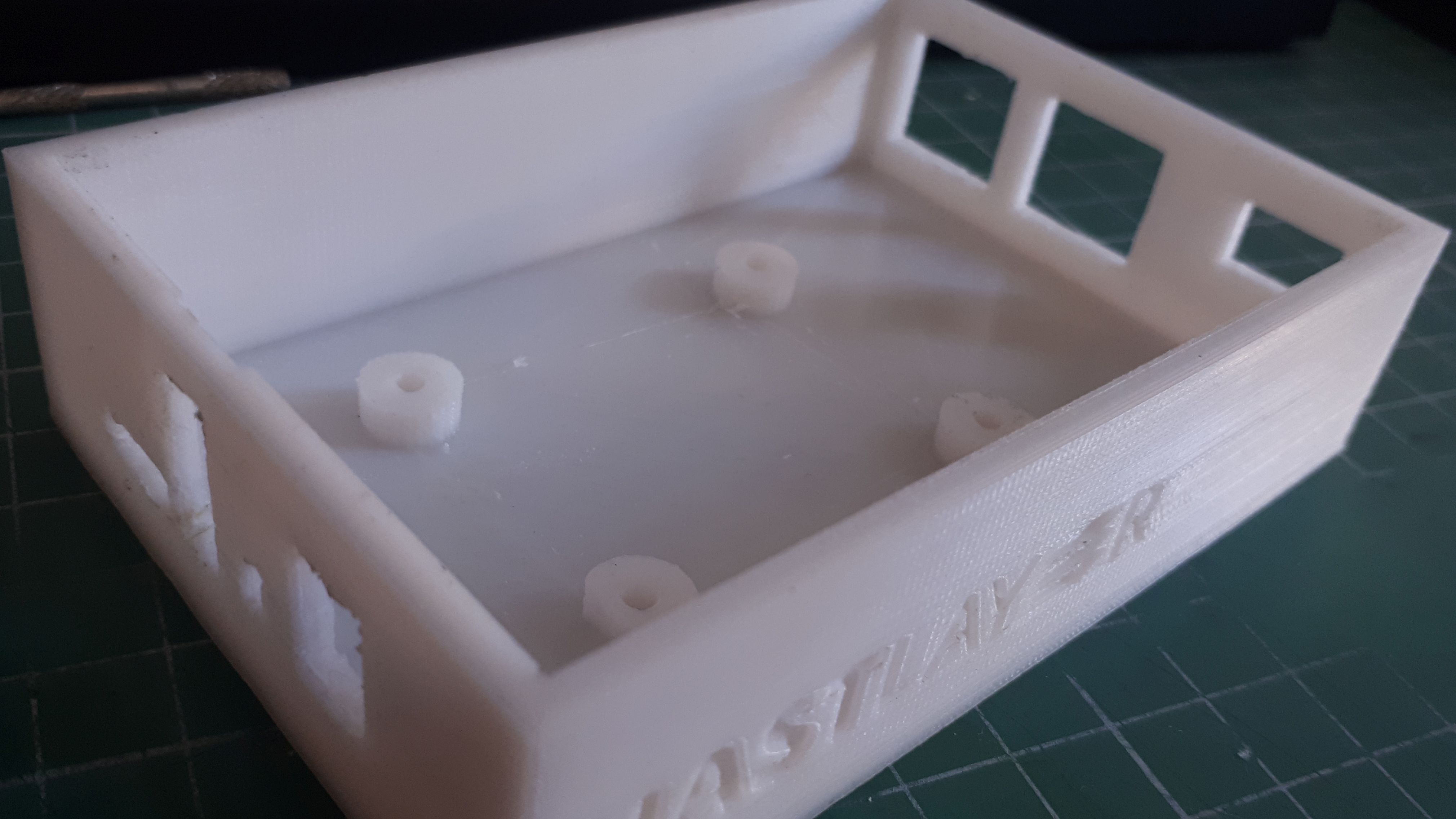
Then did a test fit. This is when you can see if the screw holes, port holes and the general layout is accomodating enough for the non-printed parts and each other. Not too tight though, once everything is good it's time to take it apart once again and see about making it look good.
Plans and Reality
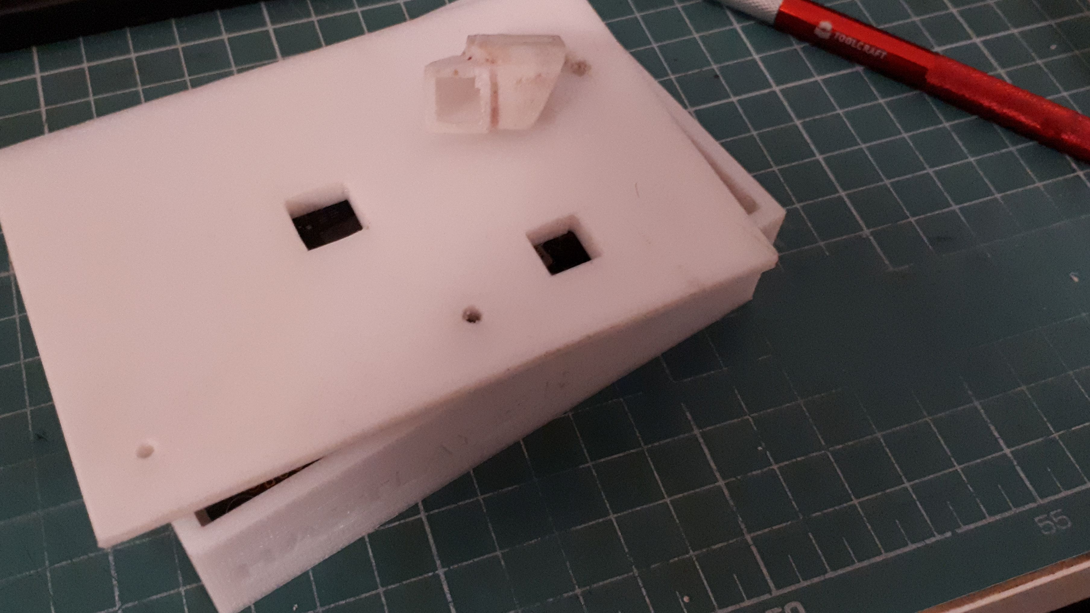
So what do when parts don't match? If both are printed parts then it's on you, fix them and print again. But if one is a specific part you have to accomodate, then you have two choices. Either iterate your printed parts until they match well, or use the material to your advantage and force it!
Both happeened in this project. When I found that the all the port holes were just a little bit lower then expected, that warranted a model adjustment and reprint. When I had that misadventure with the SMD capacitor I melted and fixed that iteration with the soldering iron but adjusted the model for future prints. When I found the fan wasn't exactly like the reference I worked with and one of its crew holes didn't match my measurements I had to use brute force. I covered the unneeded hole up with epoxy putty first. Then put the machine crew into the fan's screw shaft and started blasting with the electronic screw driver. This caused friction at the contact point on the lid until the screw melted itself int the right place. Extremely hot!
Work it!
As much as we enslave the machine, the machine enslaves us. Sure, I got a nice and precise part printed, but now I have hours of manual labor ahead of me to make a part I never would've attempted if I didn't have a 3D printer. Pretty cool, yeah?
So 3D printing isn't perfect. We get layer lines due to backlash in the stepper motor as well as wobble during more complicated motions. Yet you want a smooth and fancy looking finish right? Me too. You may ask, is there some kind of material that smooths the PLA print? Yeah, it's called elbow grease! PLA is a relatively cheap material and easy to print with but sure enough there are no shortcuts for a good finish. So once these beautiful messes of prints were done I sat down with a good series to binge and some water and sandpaper on the table. The workflow is like this:
- Go to some well ventilated area.
- Liberally spray the print with primer.
- Once dried, bring it back in.
- Lightly but quickly move it against the sandpaper until some but not all of the primer is removed.
- Repeat.
A few hours of Netflix & Sanding got me a nice enough surface on the bottom part where a final layer of paint and then some varnish could be applied. I kinda ran out of elbow grease so the air duct between the fan and the lid gets to retain its layer lines. This was my first time doing this kind of surface work so I didn't dare to go for that complicated geometry.
Another aesthetic touch, I used some epoxy putty I had around to fill the branding indentation. It can easily absorb some model paint without ruining its material properties so it can take on any color. I rubbed it into the indentation and then removed the excess with a wet retired toothbrush. I could've tried to make it flush by crapint the excess with a plastic card but I think this slightly concave surface is a good character accent.
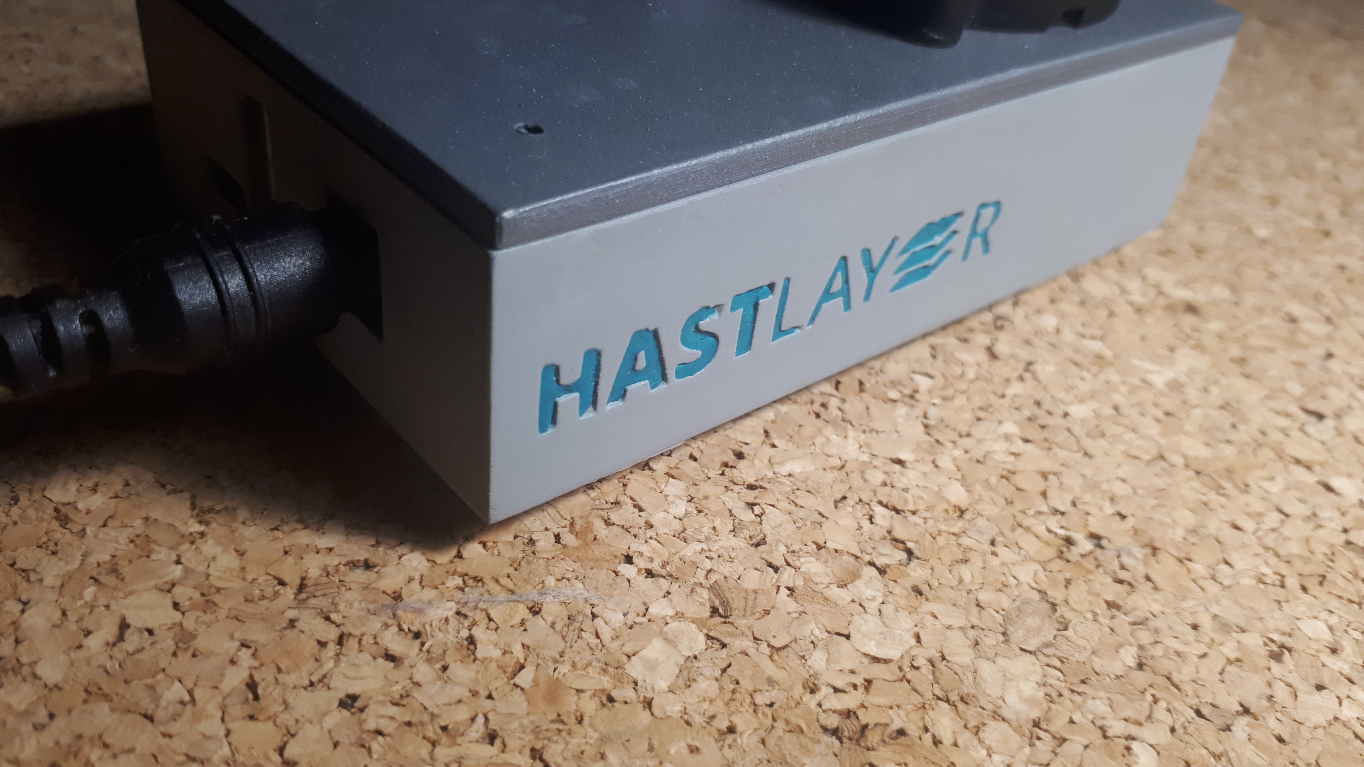
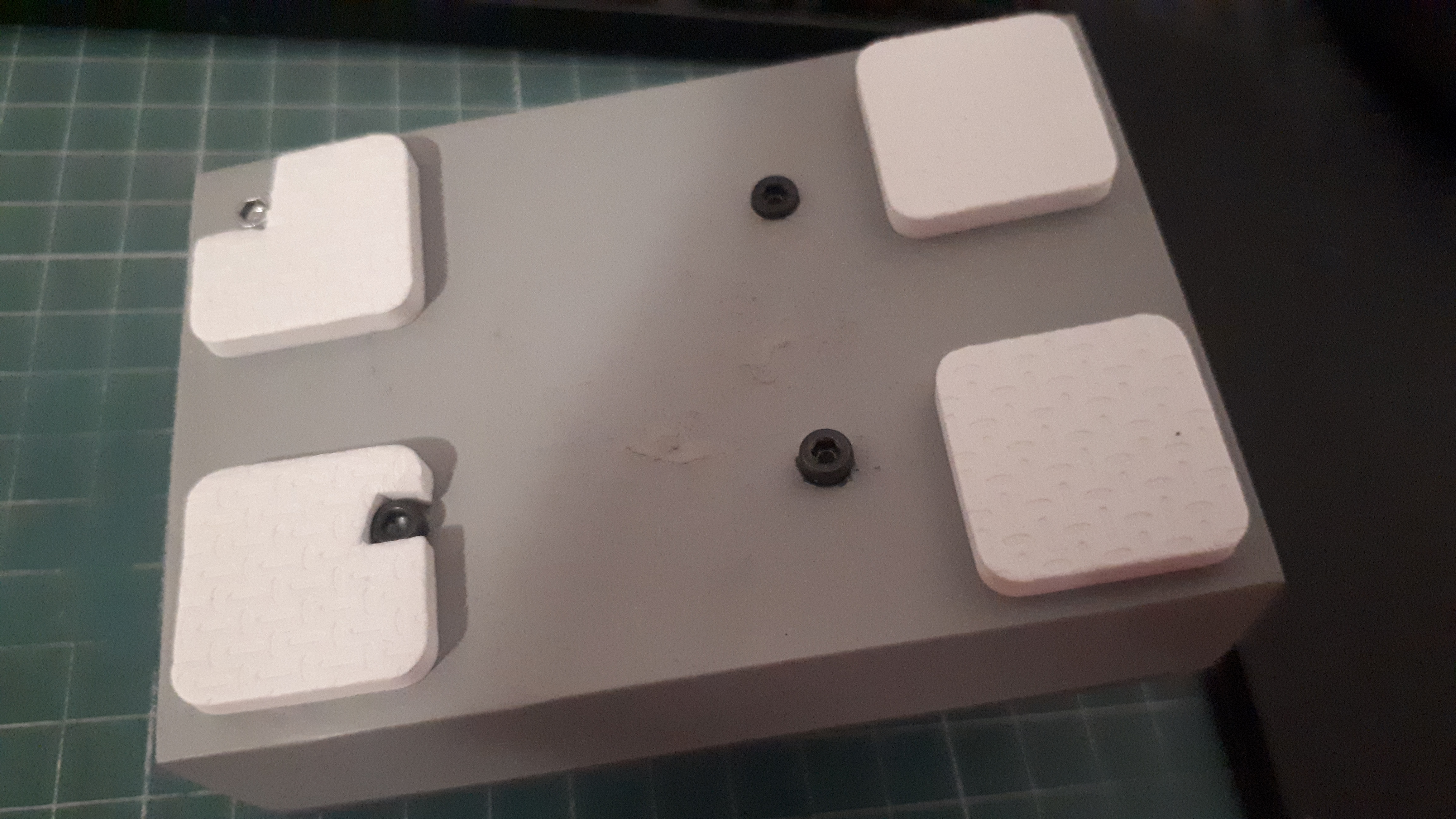
Finally I've stuck some furniture pads at the bottom so it won't be wobbly from standing on screws.
It's done: